Fairly early on, we decided on a rocket-shaped robot. Yes, it would be top heavy and was fairly likely to topple over, but it would look awesome and we like to live dangerously!
I took on the challenge of designing and building the physical robot, using the electronics designed by my teammates. It was the largest project of this kind that I have worked on, and I’ve learnt a lot!
My design process, successes and failures are detailed below.
Rockets & fireworks 🎆
I had a deadline for v1 of the rocket design – the day of my Creative Computing Club, where young people would be designing fireworks for the top of the robot!
Designing in Fusion360, I laser cut a base, some side pieces and the next couple of layers – not worrying about whether any of the electronics would fit at this stage as my main concern for v1 was attaching the micro:bit and the Neopixels to the top layer.
Not to make life easy, I attached a bearing to the middle of the top layer, allowing the whole piece to freely spin when the robot moved.
Some hasty soldering and lots of glue meant I had a working design.

Then I drove it off the table!
It mostly held together, but highlighted some major design flaws:
- There was no way to tell which was the front, which led to driving accidents…
- The layers needed to be supported by more than the flimsy side pieces.
- The wheels were too close together so it drove very strangely.
- The spinning top piece was impossible to balance consistently.
- The motors sagged and needed more support.
So time for v2!
Wheel placement 🚘
I have only ever designed two-wheeled robots before, so had never needed to put much thought into wheel placement.
I initially spaced the motors evenly around a circular base, but didn’t take into account the size of the wheels.
So when I put it together, the two wheels on each side were really close together, with a much larger gap between the two sides. This led to funky turns which almost unbalanced the robot.

I did some research on ideal wheel distance and learnt that it’s not as straightforward as I had hoped. It is all about the load, and symmetry and balance wouldn’t help because of the forces during acceleration.
I gave up on finding the perfect solution and just spaced the two wheels further apart and hoped for the best!
At this stage, all of the electronics were with Stevie, who was working on the motor driver. I had motors to test, but they didn’t have encoders on the back.
This led to some wasted time as I guessed how much space the encoders would need. After underestimating, then overestimating, I finally asked Stevie for the measurements and placed the motors the correct distance apart.
You would think this would teach me to measure things before designing, but…
Motor brackets 🔥
I wanted a neat way to attach the motors to the chassis, so had designed a case to fit around them, as on the picture above. The motor screws into the front and the base is stuck down onto the chassis.
I printed them, and all seemed fine until:
- I realised the motors with encoders are slightly different from the ones without, so that required some new measurements.
- during movement the motors sag – the single screw at the front was not enough.
A bracket to bolt the case to the chassis, and actually measuring the real motors, meant I ended up with some nice secure motor houses.
Then came the important part, printing them in red to become our rocket’s flames! 🔥
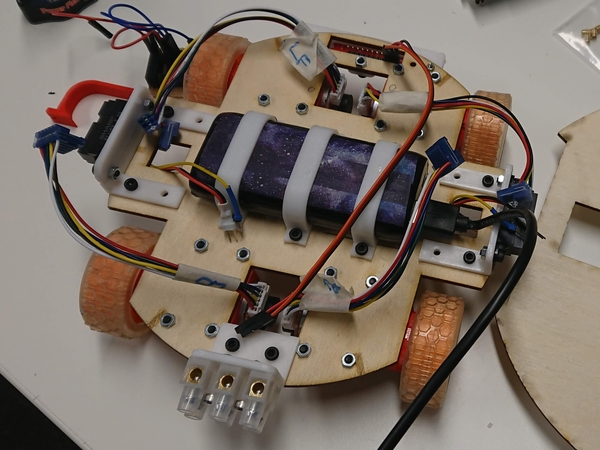
Perfecting the base 🎢
Happy with the overall design, I worked up layer by layer.
I designed brackets for all of the components and, in Fusion360, placed all of them into position, then cut bolt holes into the base layer.
After cutting and printing all the parts, I attached the ones that fit and marked on to the physical base layer to help me work out what else I needed to do.
Lots of tweaking, reprinting, tweaking again, and I was finally happy with the first layer – all the components were in position and looking good.
I did the same for layer two, which included perfectly positioning the camera to (hopefully) be halfway up the walls of the maze.
Wiring it up ⚡
I had put the motor driver on the second layer, so had to lengthen some of the wires from the encoders.
Next was adding a switch so that we can turn off the power to the motors.
I tried one I had lying around, rated to 150V and 2A, which I assumed was enough. Once it was wired up however, current was flowing no matter the position of the switch.
I tried another of the same, in case it was a dodgy switch, but had the same issue. Luckily someone let me dig through their box of random electronics, and I found a beefier switch, which works as expected.
During all of this, I also managed to dislodge some wires on the motor driver, so needed to fix that before I made it worse.
What I had assumed would be a quick job ended up taking hours, but I finally got there.

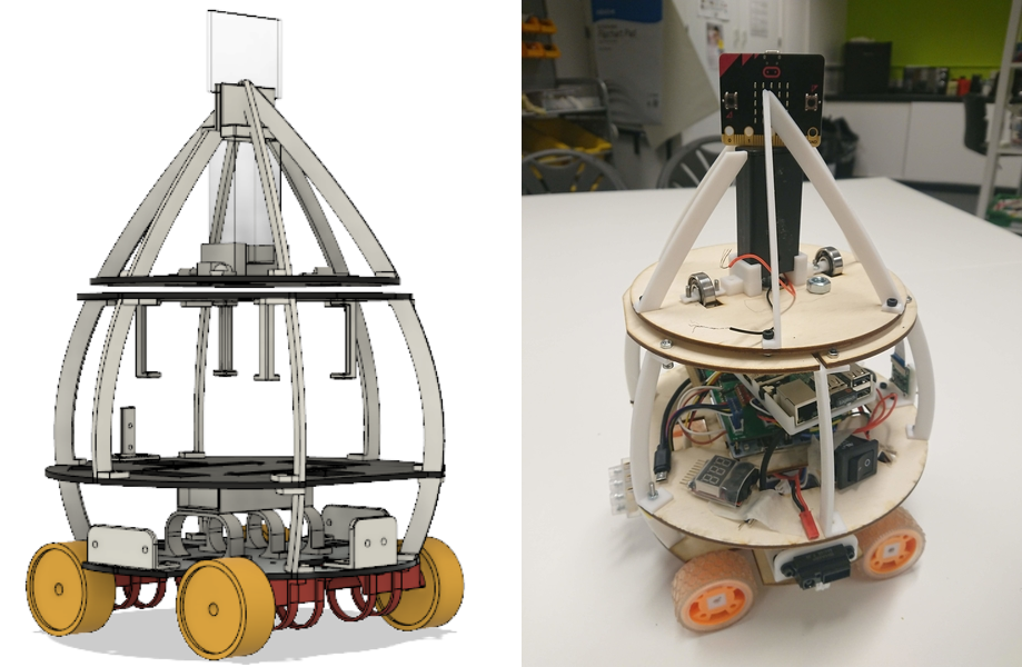
Micro:bit layer 🌈
Once I was happy with the height of the lower layers, I began work on the pièce de résistance – adding the micro:bit and Neopixels.
I decided to make things more symmetrical this time, putting the battery pack in the middle and using it to help keep the micro:bit in place.
I first used a Dremel to cut the top off the bolt in the middle (buying correctly sized bolts is for sensible people, and I am certainly not that!), then designed some more brackets to keep everything in place.
Finally, some extra bearings as tiny wheels keep it more balanced, and I have some pre-soldered Neopixels to wrap around the side pieces. I will attach the wires to the micro:bit with bolts instead of using the edge connector, giving it a neater look.
Competition ready? 🚀
Nope.
But it’s all bolted together, which means we can check if the sensors are well placed by trying to actually use them!
My Fusion360 wizardry has improved so much through this process, that I’m confident that any changes will be easy to implement.
Once the software checks are done, I’ll laser cut the layers one last time, this time from shiny black acrylic, and we should be good to go!
The final version is not as elegantly shaped as v1, but it’s much more stable, and will hopefully be less likely to fall apart on the day!
A slight sacrifice of style for practicality, but I think it still looks pretty cool.
All of the design files are on Thingiverse: https://www.thingiverse.com/thing:3494199
